TheoLt Release 10 host just been updated to support BricsCAD 18. A new download will be available shortly. If you are using BricsCAD 18 now, please contact us..
TheoLt Release 10 is GO!
Watch this space for full details of the updates, the improvements and how-to’s !
Existing users should contact us now for update details.
TheoLt, TheoLt Contour and TheoLt Tools now improve the productivity of BricsCAD to V17 and AutoCAD to Release 2017 for anyone using Total Station, Laser Distance Meters or Laser Scan Data for the productions of plans or elevations.
TheoContour R10 is coming
No, we do not post often enough here.
No, we do not update our site enough.
Yes we need to work on this.
However you can be sure when we do post, it is important, it is interesting and it is new!
In this case what is new is TheoContour R10!
Its just a week or two away – we are just finishing off the installer and testing the installer.
What can you expect from the new release? You can expect what all software developers say their new releases contain:
- More Power!
- More Functions!
- Easier to Use!
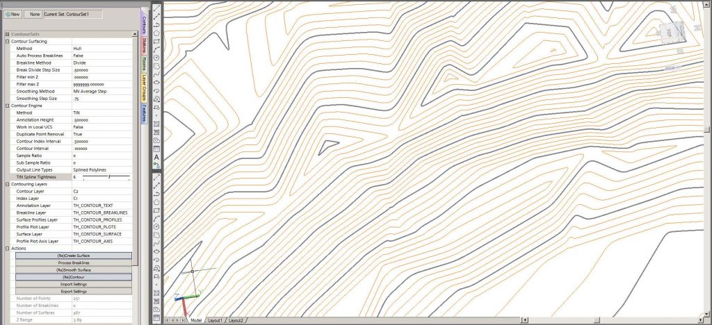
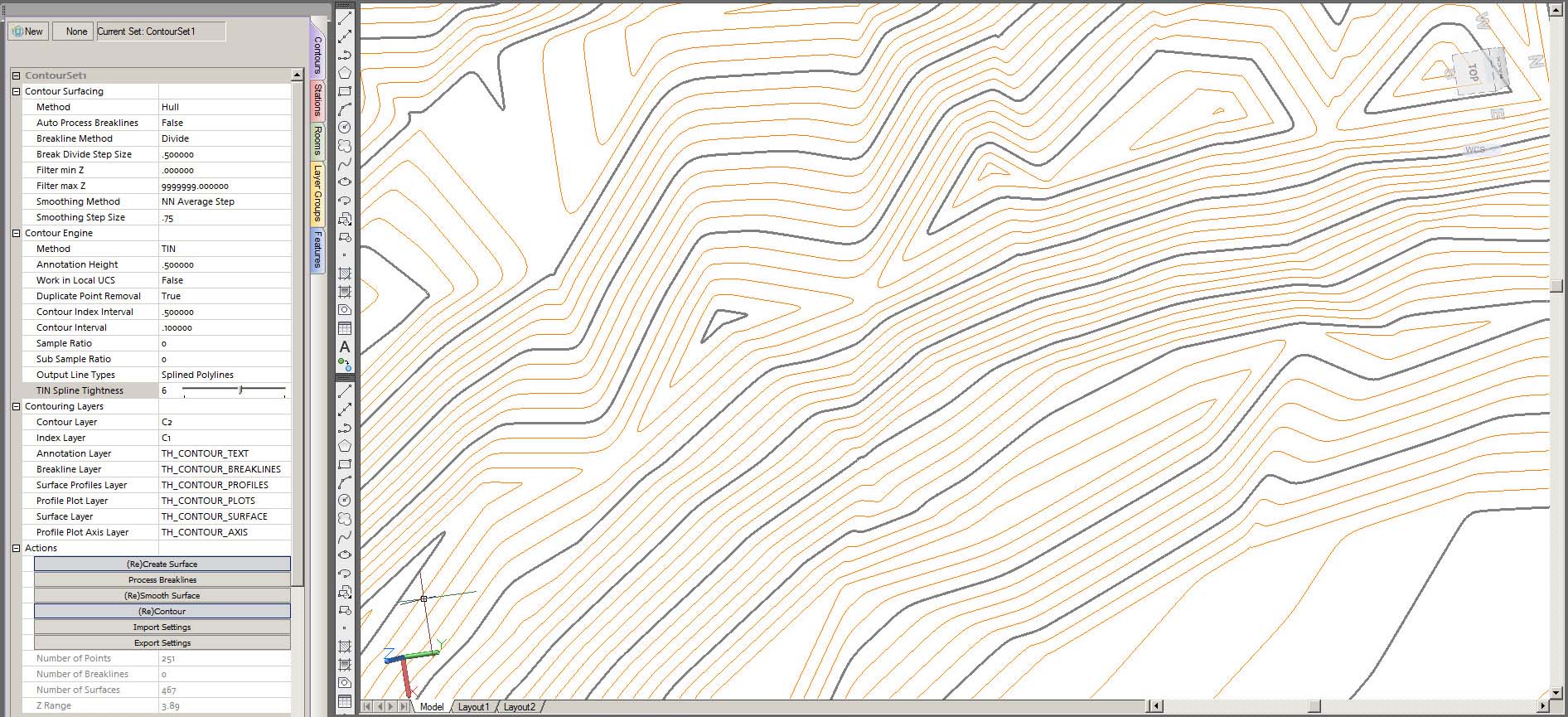
In this case it is true! TheoContour (we think) is one of the updates we are most proud of. The new features include:
- New licensing System (easier to use, more reliable, better trial options).
- PLY Import
- Powerful Surface Smoothing Options
- Powerful Line Smoothing Options
- Better Layer Control
- New Surface Creation Options with user definable colours.
- Better memory management.
Contact Us now for further details!
TheoLt R9.0
We are pleased to announce the launch of TheoLt Release 9.0
For this release our core aim has been to Streamline the Product Structure, User Interface and Settings. This is a release that has been a very long time coming but is one in which we are very proud and we believe offers a base to develop the survey tools much further than before.
A brief outline of the update follows with each module to be further detailed in posts over the coming days.
Core (Comm’s module) Updates:
- Vastly improved User Interface with “Orientation Wizard”.
- Pro: Un-occupied stations may now adjusted in Network via “data-augmentation”.
- Increased instrument library matching the latest offerings.
- Consistent Settings across ALL modules (Core, ARX’s, Contour & Office).

R9.0 Screenshot - Control.
CAD Tools (ARX) Updates:
- Support for BricsCAD V10 to V15 (including 32 and 64 bit where appropriate).
- Support for AutoCAD 2007 to 2014 (including 32 and 64 bit where appropriate) .
- New streamlined and consistent command set.
- Vastly Improved features library with far more power and customisation than before.
- theoDoor and theoDoorAlt commands allow 2 types of doors to be configured and access from the toolbars.
- New improved Icons.
- Improved Menus and menu loading (with Arx auto-load).
- Consistent Settings across ALL modules (Core, ARX’s, Contour & Office)

TheoLt Settings & Toolbars
Contour Updates:
- Contour now included in all versions.
- Contour settings and mesh now persist through save and loading of drawing file.
- Multiple mesh (TIN’s) per drawing now instead of just the one.
- New improved Icons.
- Consistent Settings across ALL modules (Core, ARX’s, Contour & Office).

TheoLt Contour Toolbar
Office Updates :
- Added, import of “level” files (gridded heights such as Nextmap).
- “Non-Pro” version with no Network Adjustment serving as a Survey Data translator for CAD
- Apply default coding to all points in a text data file.
- Network adjustment updated to match Core.
- Calculate Mesh and contour lines from points marked as “contour points” (via code list).
- Export Mesh and contours to CAD (faster workflow).
- More consistent zoom and pan.
- Consistent Settings across ALL modules (Core, ARX’s, Contour & Office).

TheoLt / Office GSI File view
If you have any questions or would like to discuss these updates, please do not hesitate to contact us: sales@theolt.com .
TheoLt 9.0 is coming!
With a new streamlined interface and a whole set of powerful new commands including a hugely customisable Feature Library, Release 9.0 is just around the corner. Watch this space!

- R9.0 Screenshot – Setup.
- R9.0 Screenshot – Control.
Whats New in TheoLt 8.22
Updates for Core:
- Support for GstarCAD in Core Module
- Expanded feature design including “step and repeat”
- Front, Back, Left or Right side alignment for default orientations (elevations).
- Settings File backups.
- Updated Manuals
Updates for Building Survey:
- Expansion of the BricsCAD tool set.
- Support for “step and repeat” inserts in features.
- Selection of just Text, Icon or both in Feature Folders (Plan Builder)
- Flip inserted features in 4 directions (aleviating the need to always choose the same point for insert).
- Updated Manuals
Are you aware of the “Pro” version? This includes;
- Full Least Squares network adjustment (traverse)
- Instrument motor control
- Contouring
Request a trial now.
Elevation Views in AutoCAD
One of the most frequently asked questions by TheoLt users is:
‘How do I get an elevation view of the building I’m measuring?’
TheoLt sends 3D data to AutoCAD which is plotted in the lines and layers of your choice. It is useful to be able to vew the drawing as a façade. One method to achieve this is to use AutoCAD’s UCS (User Co-ordinate System) command to set up a façade UCS and view it square on. The 2 key commands are ‘UCS’ and ‘PLAN’. This example is a job started in WCS:
1. Place a polyline across the plan by snapping to the ends of a measured line (because this will guarantee the UCS will be true level) It’s the red line across the facade here:

2. Fix a UCS to the polyline. Use the UCS ‘e’ option (for ‘entity’ or ‘ob’ for object in late versions) to pick the polyline when prompted. Use ‘Plan’ to get a plan view of the new UCS.
3. Rotate the UCS about the required axis by 90 deg to point the Z axis at the viewer of the façade. This is done by entering ‘UCS’ on the command line and then the axis of roatation (x, y or z) then the angle, the default is 90deg. Watch the UCS icon to see what is happening.
4. Use ‘plan’ to get a plan view of the new UCS
5. (optional) Use UCSICON command to set ‘Noorigin’ to get the icon out of the way..
6.Save the UCSwith an apropriate name (‘Front’ ‘Back’ North ‘Elavation’ etc) with the ‘S’ option at the UCS command for future use.
Enjoy your facade view!
TheoLt will plot lines true to the instrument orientation in AutoCAD regardless of the UCS. View-ports in model space can be used to run plan and elevation drawings at the same time. The façade UCS is also useful when setting up views of the 3D data for elevation drawings.
You can also use the AutoCAD ‘View’ command to save views too as a short cut to getting back to a view you like. Once the façade view is as desired it can be named for future use.
Tip: I find it helps to use your hand in the same way as we did to learn Flemmings Left hand rule (assuming you have your mouse in your right hand!) in physics at school to work out the required axis of rotation at 3:

This is a useful method of setting up a facade UCS if your job isn’t aligned to the WCS : don’t forget TheoLt’s Default Orienation option to orient aligned with a plane which is great for quick starts aligned to a facade.
Traversing with Historic Scotland

Historic Scotland are investing in survey! As part of their development of a minimum site record we do a training exercise in travserse control. I am asked to trouble-shoot their field kit, update to TheoLtr8.1.6 and take 3 teams through network observation and adjustment. The practice site is Blackness Castle and the weather is cold but, mercifully, dry.

We rattle through setting up, do a 4 stn loop, make a mess of station naming, recover and head off to the paraffin perfumed barrack block to check the results. We work through our data and run the calc, the results are superb! The network is adjusted and applied and we enjoy a good buffet lunch before tackling 3 networks in 3 teams.
The new station name editing feature has improved using user defined station names at capture. The great thing about netadjust in TheoLt is the real-time aspect, poor shots are flagged as measured and preview calculations and diagrams can be run, all on live data. Traversing is all about procedure and adapting to new ways of working can make simple things difficult, it always takes patience to get procedures right and we have to make a few re-starts before we get the sequence to suit the situation.
 Taking out the ‘brown’ data is a good starting point for analsing the network.

Taking out the poor shots, running the calc and seeing the result can prompt you to take more obs or, in this case, shave 10ths of a mil off an adjusted station position: a far cry from the days of Bowditch and the calculator!
Because TheoLt works with live station properties station names have been on a like- it -or- lump- it basis until release 8 when it bemame possible to use a custon station name. This is a surprisingly useful improvment as there occasions when station names are pre-set from existing survey or when station ocupation is in decending order, in the past renaming was only possible as an AutoCAD edit post-survey, now the name can be set at Default Orientation or when the station is set out.


Customisable station naming is one method of working with pre-declared station identities, station names can now be determined at setting out adding a new level flexibility to control operations.
This relatively simple addition to the functionality of Netadjust in TheoLt 8 has a great impact on workflow. Whether you are occupying existing control, adding stations to an existing network or creating a new network from scratch, Theolt now affords the Surveyor the optimum realtime platform for Control networks.
TheoLt Real-Time Network Adjustment offers a new workflow whereby the network benefits from:
- Review of each observation- Interactive rejection of observations with real-time results update
- The ability to ensure each station is complete before moving
- Computation of Resections with multiple face oberservations.
- Adjustment of CAD drawings to network- Live diagram in CAD

So before you put your kit back in the box you can be sure your network is delivering what you need!
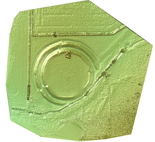
A record survey by PhoToPlan
Drainage problems with the pavement on the gun deck of Martello Tower 24 this tower required a full record of the historic paving prior to lifting for English Heritage.

This is a rectified montage of the gun deck pavement and firing step of a Martello tower. It was achieved by 4m PAP (Pole Aerial Photography) in a single day on site. The pavement level is a stitch of 9 images, the firing step 12. The images were rectified in PhoToPlan and then balanced and feathered in Photoshop.
Control for the rectification was by REDM to detail points collected in TheoLt:

In this plan I plotted the wall top from intersection in PhoToPlan 3D, orientated to the same control points from our reconaisance KAP imagery:

This tower is impressively armed with a mighty 24pdr; we had to wait until it was lifted before we could record the pavement condition in advance of works to stop the leaking, visit when it rains and you get wet!

Once the pole is set up and the rig hoisted it’s a case of working as quickly as possible to get even illumination across the whole photo block…and taking advantage of rare moments of excitement like the bit where we have to negotiate the flag pole.

For completeness the pavement survey was required to cover the firing step so the images are rectified again but this time to the firing step plane. The control points are snapped onto the joint lines from the TST survey by TheoLt. 12 images got me around the ring.

I had hoped there would be a deep enough chord of the circle covered in each shot to make use of the minimum number of points I measured to describe the jointing of the circumference rail support blocks, this turned out to be the case but more points would have been better, some of the projected images came out a bit stretched!
![]()

Next the central pivot column is rectified so that the final montage is presented to a consistent scale:

The pivot post is easy: 6 points and its done! Bringing the pieces together completes the cover:

The 3 planes are combined into one single orthographic projection, there was a great deal of fitting needed to get the coverage of the pavement right up to the base of the central pivot post from oblique imagery taken with the pole on the firing step.
Re-inserting the montage back into AutoCAD and checking by PhoToPlan rectification showed a 9mm average discrepancy between the montage and the control points.
This documentation project is a great example of what can be done with PhoToPlan, Photoshop, AutoCAD TheoLt and….

…a camera on a stick!…
So in 4 easy steps we got from ‘no cover’ to ‘ortho’ cover.
TheoContour: Fast Contouring made easy!
You can spend a lot of money on contouring, the software tools for surface interpolation and depiction do not come cheap and even the ‘inbuilt’ AutoDesk options require a hefty investment in a ‘Map 3D’ or ‘Civil’ variant. But there is a very effective and low cost option which I have been using for some time now and it’s proved itself to be a good ‘fast and dirty’ fix for getting contours done: TheoContour.
Like all of the Latimer CAD family of tools this is based on the premise of solving a CAD problem, not a surveying one: there are no data tables to code, no CoGo computations to step over and the outputs are pure CAD entities ready for your next DWG based task. And of course all is in 3D from the start.
Let’s start by looking at the results:
This composite view gives you an idea of what TheContour is capable of: annotated smooth 3D ploylines and shaded surface generation.
So how does it work?
TheoContour is an arx/brx application:
 it works with points so getting started is easy: just get your points into AutoCAD! The points can be layered anyway you choose, and obviously, they need to be congruent in terms of height consistency ( in other words they have to be organised such that the Z values are correct!)
Once we are happy all the points are in the current view in WCS the 1st TheoContour command is : theocollate which loads up the points and reports on the surface they describe ready for the next step:
 I kid you not, the arx processes this stuff pretty quickly 2,703 points in about 3 s!
Note that the command line report relays the settings we are using on this model. They can be changed easily; I’m not happy with contours at 4 to the metre indexed on the metre so I go to settings and switch the index interval to 5: 
I’m now ready to contour: 
The command is, you guessed it: theoContour! Plotting the contours takes a little time, this example takes about 45s to generate. Some models can take a while, it’s all dependent on how fine the contours are combined the entity type being generated (lines, polylines or splined polylines).

Not bad for a 1st pass, I would return to the settings and look at smoothing but this gives you a good idea of how simple the process is: and it’s flexible- in effect the datum is the zero value for Z in the current UCS so you can use theocontour to generate contoured surfaces indexed to any plane defined by a UCS! The contours are 2D ploylines in 3D space so they can be edited easily using PEDIT to get them tidy!
So just using 2 commands and tweaking the settings I have got working contours in minutes.
TheoContour also generates profiles and shaded surfaces, the text annotation is pretty neat too but for now I just want to show how simple contouring CAN be if you use TheoContour!

TheoContour can be downloaded as part of TheoLt core at:…